Measuring distributor advance and setting the ignition
timing
with a stroboscopic timing light on Citroën D models
One of the basic, yet most important
steps in a
proper tuneup on any car is setting the ignition timing. On a Citroën
D,
this is no simple task. Most of us have avoided the problem by
resorting to
time-tested methods based on guess-and-by-golly, or perhaps on more
refined,
yet not exacting methods such as turning the distributor to obtain
maximum
power, yet avoid ping or "pink", as Europeans have tended to say.
A great deal of time and effort has been
expended
on this vague aspect of maintaining our cars. This need not be. The
fact that
our cars went through most of their design life with no timing marks is
absurd,
but that does not deter us from loving them. In fact, it adds to their
uniqueness and it should also add to the satisfaction of answering the
challenge of getting our cars running tip-top. Even those of us with
cars that
came with timing marks may be daunted by the timing procedure. I have
decided
to make an attempt to de-mystify this vital step in getting all of the
power
and reliability we can from our cars. To perform a basic tuneup you
will need:
- a fresh breaker point set
and condenser
- cleaned, restored
distributor, ideally, with advance mechanism matched, unchanged and
unaltered
- a tube of point grease,
or high temperature thick grease
- a test light of the same
voltage as the electrical system of your car.
- a copy of #814 or #583
Characteristics, Adjustments and Checks manual (C&A) Download
here.
- A copy of the updated timing chart. The original found in
814 and 583 does not include U.S. specification. Most of them are here.
Let's start with the basics. We will
assume that
the car we are discussing has been unaltered and that it has all of its
original parts. Every engine that comes off the assembly line has a
carburetor
and a distributor matched to give optimum performance. Ignition timing
is
controlled by interaction of the distributor and the rest of the
engine, while
the carburetor must deliver the right ratio of fuel and air in every
condition.
The first step in any tuneup is to install a fresh set of points and a
healthy
new condenser. The new point set should have a dab of high temperature
grease
applied to its bumper so it does not wear excessively as it rubs
against the
distributor cam. Old grease should be removed from the cam, and the
distributor
should be in good condition. The point gap must be set to
specifications.
While a dwell meter can be used, it is more important that the gap be
wide
enough so that, as cam bumper wear inevitably occurs, it does not make
the gap
close prematurely. This is why I simply set them to the maximum
allowable
opening. This, along with proper cleaning and lubrication of the point
bumper/cam, ensures a long lasting tuneup.
If you own a Citroën D, you should by
now be
fully aware of the lack of technical support in places such as the
United
States. It therefore behooves us to be armed with all of the necessary
tools to
maintain your own cars. Despite the seeming complexity of the D, for
the most
part, they are not that difficult to work on and they are famously
robust (except
for rust). One of the most important tools to have is a complete set of
manuals. The other indispensible tool is the Citroen D email
list at CitroenDSID.
Subscription is free and really risk free. There you will be able to
get in
contact with people who can solve most any problem you may encounter.
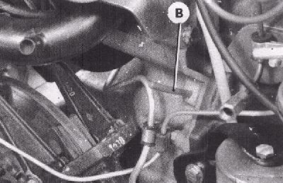
Once the distributor has been properly
serviced,
it must be installed in the car and set to static time. Because D's
have no
external timing marks, except for the latest ones, the flywheel must be
locked
into position and the distributor set using a test light. A specially
made pin
(B) or a 6 mm drill bit is inserted into a hole in the flywheel
housing,
hidden under the alternator. It is a rite of passage for D owners to
discover
that diabolically hidden timing hole. Once you find it, you will swear
that you
can now find the Holy Grail! The first time is the hardest time to find
this
hole. You may have to remove the left front fender to be able to see
it. Later,
you might get away with a strategically placed light and a mirror. This
alone
is reason enough to switch to using a timing light!
The flywheel must be rotated until the
pin drops
into a slot in the flywheel, locking the crank at a specific point,
then set
the distributor can be rotated until the points just open. Touch the
tip of a
test light between coil (-) and a good ground. If the ignition switch
is turned
on, the light should glow when the points are opened. This is where
many of us
stop, and the car will run, but not as well as it should. The
C&A
manual clearly states that the timing should then be set with a strobe
light to
complete the job. Whenever you use this pin, make absolutely
certain that
you remove it before you start the engine or try moving it in any way.
The pin
will break off and the end will stay in the slot of the flywheel,
damaging your
engine!
Most any other car has a ready means of
setting
the ignition timing using a strobe light. Here is where it gets tricky
for a D
owner. Our cars have no access to a component that spins at crank
speed. The
flywheel is buried, and there is no drive pulley off the timing chain
end of
the engine, which is pointing rearward. However, there is an accessory
drive
pulley that runs off the camshaft, which spins at exactly half the
speed of the
crank, and that is what we will use. But timing specifications are
almost
always stated in crank degrees, so setting time from the position of
this
pulley will require this factor to be taken into account. 20 degrees of
crank movement
will produce 10 degrees of camshaft/drive pulley movement.
To add to the confusion, for U.S. spec
cars, the
static timing point is 0 (TDC) starting in November, 1967. Cars built
for the
European market have the static timing point on the flywheel set to 12°
before top dead center (BTDC). In July, 1971 European cars caught up to
U.S.
spec emission requirement and they too changed their flywheels to TDC.
On fuel
injected engines built after July, 1971, the offset is 8 degrees, 30
minutes
BTDC. These factors must be accounted for when calculating the strobe
timing
point. As you will see, you cannot just subtract 12 and get the right
timing
point.
Compensating for the advance curve of
the
distributor piles on even more confusion. As I stated earlier, every
engine has
been matched at the factory with its own distributor. A quick look at
the
advance curves shown in the C&A manual will show that the advance
curve on
many of our cars begins very soon after 0 rpm and moves upwards at
varying
rates and ends at varying speeds. This is controlled by the advance
mechanism
located under the points plate in your distributor, which is rotated to
effect
timing during various driving conditions. The mass and shape of the
weights,
the strength of the springs and the location of the stops determine the
advance
curve for each distributor and are specific to engine type and year.
Because
the timing begins to change as soon as the engine begins to run, if you
simply
set the time at idle speed, you will get an inaccurate reading. This is
why we
must determine the maximum advance speed and set our time while the
engine is
running above that point using the advance curve specifications
specific to our
cars. To proceed, we will need some tools. We will need
- A timing strobe light. It
need not have advance compensation. Lights that are not powered by the
battery are notoriously dim, and are therefore hard to see even in low
light, and should not be used. It is simply unsafe to use them.
One can easily get them and your fingers tangled up with the fan.
Ouch!
- A timing scale, either a
factory made tool, 3078-T or you can make one yourself, using this
drawing as a guide. Click here to view.
Right click and use "save target as" to download it.
- A copy of the
C&A manual, turned to op. 210-0 "Checking and Adjusting Timing".
- Download
a copy of the timing specs for most D's here
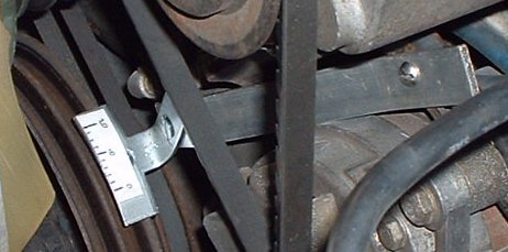
Here is the one I
made. All of the
parts came from the local hardware store. The tool is made from a "T"
bracket and a narrow piece of aluminum flat stock. The base leg is bent
up
90° while the ends of the other 2 are shortened slightly and curved to
follow the radius of the pulley. The bar is cut to required length and
has 2
bends in it to allow clearance and proper offset. First the bracket is
attached, then tilted to the correct angle. Then this assembly is held
against
the alternator tensioner and marked from behind for drill hole so
the
face of the timing tool is just away from the pulley. A screw goes
through the
front of this hole, through the slot in the alternator tensioner brace,
then an
oversized nut for spacer, a washer, then a nut to secure all. When
satisfied
with fit, tape and/or glue a timing plate made from paper. Marks are
1/8"
apart. Each increment equals 2 deg. The tool must not rub or interfere
with the
various moving parts, yet hold the scale close to the edge of the
accessory
pulley.
The flywheel is then locked into static
time
position using the hole in the flywheel housing and the pin. Whenever
you
use this pin, make absolutely certain that you remove it before you
start the
engine or try moving it in any way. The pin will break off and the end
will
stay in the slot of the flywheel, damaging your engine! Use a sharp
punch
to make a clear mark on the edge of the pulley adjacent to the "0"
point on the scale, or just use a dab of bright paint. Remember that
this does
not necessarily represent TDC. It is merely a reference point, unless
your
engine happens to have TDC static time.
Now we can apply some basic mathematics
to this
situation. Remember that the distributor runs off the cam and is also
turning
at half the crank speed, therefore distributor time is the same as cam
time.
For the sake of demonstration, lets pick out one of the advance curve
charts
located in the 814 manual. We will work on a 1967 DX European spec.
engine. The
correct chart for this engine C-6, which appears to top out at 9
degrees
distributor time at 2500 RPM. To obtain crank time, we double this
number. Then
the static timing point must be subtracted to negate the offset caused
by the
static timing point. The resulting number must again be divided by 2 to
convert
back to cam time. So:
if D = maximum
advance in
distributor degrees (same as cam degrees) and
S = static timing offset, then
2D - S / 2 = T
T being the reading at a scale mounted on the accessory drive
pulley.
If D = 9 and
S = 12 , then
2 x 9 - 12 / 2 = 12.
With this, you simply set the distributor rotation to 3° on the scale
at
3000 r.p.m.
This chart can be used as a guide to set
time on
any D engine, even the dual point 3 bearing engines found in Traction
Avants
and early D's. Click Here. This
chart, along
with the timing advance graphs located in the C&A manual, may help
you to
find the correct distributor for your engine, should you find that
yours is
incorrect or damaged beyond repair. Fortunately, there is not a really
large
number of possibilities, and the distributor numbers are also located
there to
help you in your search. Remember that the correct advance curve
matched to
your engine along with accurate timing will give you optimal
performance and
efficiency at all speeds.
For owners of U.S. spec cars, the job is
just a
bit more of a challenge. For cars built before 11/67, the Euro timing
curves
should be OK for U.S. cars and therefore, you can use the Euro
procedure. Until
November of 1967, the static timing offset is the same as European
cars, when
they begin using a flywheel with TDC timing set point. I have Service
Bulletin
L-160, which has a curve for the 1967 U.S. spec. DV motor. The curve is
identical to the one found at chart C8, as found in op. 210-0 in the
C&A book.
This formula also works with European cars built after July, 1971,
except fuel
injected cars built after July, 1971, which retain an offset, S=
8°30'. Since U.S. spec cars after 11/67 have their timing holes at TDC,
the
static point correction need not be done. But the formula still holds.
2D - S / 2 = T, with S=0 so
2D/2 = T or just
D = T
It may seem therefore, that a timing
light is not
necessary, but to get repeatable, accurate timing and to avoid the
necessity of
using a flywheel locking pin and test light, this is still far more
practical.
Even though we lack our advance curve charts, all is not lost; we
simply will
need to go one step further. We must discover our maximum r.p.m.'s and
your
maximum advance. The following procedure will reveal this. You will
need to
have your scale mounted, your zero point marked on the accessory pulley
using
the flywheel pin and test light. Attach a tachometer and a timing
strobe light
to your engine. Start the engine and point your light at the pulley and
scale. Make
certain that you have not left the flywheel locking pin in, if you
first set
your static timing point. Begin to rev the engine slowly upward.
You should
not have to go beyond 3000 r.p.m. As the speed increases, you should
see the timing
mark begin the climb up the scale. Write down the maximum degrees and
note your
r.p.m.'s at that point. This is your maximum advance. From now on, you
can set
your time to this point using just your timing light. If you are not
sure that
the distributor is correct for your engine, this procedure can also be
used to
construct your own advance chart. Simply note advance at several
r.p.m.'s and
lay out your results on a chart like the ones in the manual. You can
then
easily compare yours to the book's.
Using a timing light is not only
practical, but it
is a foolproof way to reset our engines to proper time on a consistent
basis
during tuneups and other types of engine work. Even if you find that
regional
differences in fuel quality, altitude, variations in the condition of
our
engines, distributor mismatch or any other factor still cause our
engines to
ping, we can at least have a known starting point for our adjustments.
While I am pretty sure that I have this
all
reasoned out pretty thoroughly, and I have written it in a way that I
hope you
will be able to understand, I am open to suggestions. If you find
discrepancies
or if you can offer some constructive criticism, please email me.
updated 03/12/2024, Copyright 2024, Mark
L.
Bardenwerper, Sr.
Many thanks to Rick Levy and Joe Conte for their technical help and
their keen
eyes!